


Description
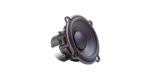
JL Audio 12W3v3-2
12-inch (300 mm) Subwoofer Driver, 2 Ω
This powerhouse 12-inch driver delivers potent performance and world-class sound quality in medium power applications. Several exclusive JL Audio technologies and proprietary assembly techniques are applied to the JL Audio 12W3v3 to enhance linearity and reliability.
![]()
Dynamic Motor Analysis - DMA Optimized Motor
Summary:
JL Audio's proprietary Dynamic Motor Analysis system is a powerful suite of FEA-based modelling systems, first developed by JL Audio in 1997 and refined over the years to scientifically address the issue of speaker motor linearity. This leads to vastly reduced distortion and faithfully reproduced transients... or put simply: tight, clean, articulate bass.
Detailed Information:
Since 1997, JL Audio has been at the forefront of Finite Element Analysis-based modelling of loudspeaker motors and suspensions. This research is aimed at decoding what we refer to as the "Loudspeaker Genome"... a project aimed at understanding the true behaviour of loudspeakers under power and in motion. A major component of this integrated system is DMA (Dynamic Motor Analysis). Starting with the 15W3 and the W7 Subwoofers in the late 1990s and early 2000s, DMA has played an important role in the design of all JL Audio woofers sold today, including our component woofers.
DMA is a Finite Element Analysis (FEA)-based system, meaning that it takes a large, complex problem, breaks it down into small solution elements for analysis and then assembles the data to form an accurate, "big-picture" solution. DMA's breakthrough is that it actually considers the effects of power through the coil as well as coil/cone position within the framework of a time-domain analysis. This gives us a highly accurate model of a speaker's actual behaviour under real power, something that the traditional Thiele-Small models or other low-power measurements cannot do. Because DMA does not rely on a steady-state model, it is able to consider shifts in the circuit elements being analyzed. These modelling routines are intense, requiring hours to run for a whole speaker.
DMA is able to analyze the real effects of fluctuating power and excursion upon the magnetic circuit of the motor, specifically the dynamic variations of the "fixed" magnetic field. This delivers intensely valuable information compared to traditional modelling, which assumes that the "fixed" field produced in the air gap by the magnet and the motor plates is unchanging. DMA not only shows that this "fixed" field changes in reaction to the magnetic field created by current flowing through the voice coil, but it helps our engineers arrive at motor solutions that minimize this instability. Analyzing this behaviour is critical to understanding the distortion mechanisms of a speaker motor and sheds light on the aspects of motor design that determine truly linear behaviour:
- Linear motor force over the speaker's operational excursion range
- Consistent motor force with both positive and negative current through the coil
- Consistent motor force at varying applied power levels
Our ability to fully analyze these aspects of motor behaviour allows our transducer engineers to make critical adjustments to motor designs that result in extremely linear, highly stable dynamic loudspeaker motor systems.
The payoff is reduced distortion, improved transient performance and stellar sound quality.
![]()
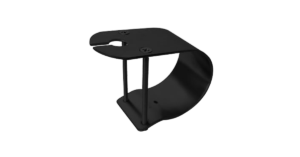
Elevated Frame Cooling
Summary:
JL Audio's patented Elevated Frame Cooling design delivers cool air through slots directly above the top plate to the voice coil of the speaker. This not only enhances power handling but also sound quality by minimizing dynamic parameter shifts and power compression.
Detailed Information:
Many speakers employ venting techniques to enhance voice coil cooling. This is typically accomplished by having big holes in the sides of the frame just below the spider attachment shelf. While it provides a modest cooling benefit, this low-velocity air flow does not blow directly or strongly on the voice coil.
Our patented design improves upon this cooling technique in a number of ways. By elevating the frame above the top plate of the motor (via stand-offs integrated into the bottom of the frame) a narrow, high-velocity air path is created between the bottom surface of the frame and the top surface of the top plate. This air path leads directly to the voice coil and then turns upward into the spider air cavity. By utilizing the pumping action of the spider through this focused air path, a large volume of cool air hits the coil windings directly.
Another important benefit is that the upper surface of the top plate (one of the speaker's hottest parts) is directly exposed to cooling air flow, whereas on a conventional design it is isolated from the airflow by the lower flange of the frame. The elevated frame technology greatly increases thermal power handling, reduces compression effects and does so without any additional parts.
![]()
Floating Cone Attach Method - FCAM™
Summary:
This assembly technique, conceived by JL Audio, ensures proper surround geometry in the assembled speaker for better excursion control and dynamic voice coil alignment.
Detailed Information:
JL Audio's patented FCAM™ technology is an innovative method of bonding the surround/cone assembly to the voice coil former/spider assembly. This feature helps ensure concentricity of the surround, spider and voice coil without torquing the suspension to achieve it. This allows for the inevitable, slight variations in production part dimensions without having them negatively impact the integrity of the suspension and coil-centring at high excursions.
![]()
Vented Reinforcement Collar
Summary:
JL Audio's Vented Reinforcement Collar (VRC®) improves the rigidity and stability of the cone/spider/voice coil junction and directs airflow over the voice coil windings for improved thermal performance.
Detailed Information:
The Vented Reinforcement Collar (VRC®) is a composite structure that addresses two issues related to reliability.
By reinforcing the critical junction between the cone, voice coil and spider, the VRC greatly reduces failures due to glue breakdown or material weakness. It does this by greatly increasing the adhesive contact area and providing stress relief to the spider material at excursion extremes.

The VRC™ also features slots that facilitate airflow directly onto the voice coil windings. This reduces thermal compression effects and enhances reliability.
Current versions of the VRC™ also incorporate lead-wire strain relief structures to improve mechanical reliability.
![]()
Insert Molded Suspension / Coil / Terminal Sub-Assembly (U.S. Patent #7,379,558)
Summary:
Spiders, voice coils, terminals and lead wires are preassembled, using a patented process, onto a composite carrier for improved precision and reliability.
Detailed Information:
A conventional speaker is assembled in layers. In other words, multiple parts are assembled and glued sequentially into the basket, leading to stacking of tolerances and making it difficult to achieve optimal assembly precision.
JL Audio's patent-pending insert-moulded spider carrier permanently bonds the spider to a mechanically robust carrier that also incorporates the terminal assembly and lead wire strain relief features for enhanced reliability and optimal alignment of parts. This subassembly is assembled outside the speaker basket, for optimum alignment and glue-joint integrity. The benefit is a more precisely built, more mechanically sound loudspeaker.
![]()
Customizable Trim Ring
Summary:
This removable ring can be painted to match the installation theme and directly receives JL Audio grille mesh inserts (sold separately).
Detailed Information:
This ABS trim ring is moulded in black, but that doesn't mean it has to stay that way. By custom painting it, you can match your installation theme and create a personalized look.
Specifically-designed grille mesh inserts are available separately and fit into the inner diameter of the trim ring.
Helpful Tip: Installing the grille mesh inserts is much easier before mounting the woofer into the enclosure.
![]()
Engineered Lead-Wire System (U.S. Patent #7,356,157)
Summary:
Carefully engineered lead-wire design and attachments ensure controlled, quiet lead-wire behaviour under the most extreme excursion demands.
Detailed Information:
Managing the lead wires on a long-excursion woofer is one of the trickier aspects of its mechanical design. To address this, many long-excursion woofers today rely on a simple solution that weaves the lead wires into the spider (rear suspension) of the driver.
The biggest problem with this approach is that spider-limiting behaviour plays a hugely important role in a woofer's performance. Lead wires that are attached or woven into the spider material can alter the spider's "stretching" behaviour. The tinsel wire naturally has less 'give' than the fabric material of the spider leading to asymmetrical spider behaviour and non-uniform stress distribution around the spider circumference. The wire attachment points can also cause localized pulling and tearing forces at the spider's excursion limits. As such, longevity becomes a major concern and makes the woven-in design less than ideal for very long-excursion designs.
While a traditional 'flying lead' design does not compromise spider linearity or radial stability, it creates its own challenges on a long-excursion woofer. Managing the 'whipping' behaviour of the wire and making sure it does not contact the cone or spider is one challenge. Another is ensuring that the leads do not short one another or the frame of the woofer.
To overcome these issues, JL Audio's engineered flying lead-wires work in conjunction with carefully engineered entry and exit support structures moulded into the terminals and the voice coil collar. Some models also feature jacketed lead wires to further reduce the likelihood of shorting and fatigue. The result is flawless high-excursion lead-wire behaviour, with outstanding reliability and none of the compromises inherent to a woven-in lead wire system. Building woofers this way requires much more labour and parts complexity than the simpler woven-in approach, but the payoff is in reduced distortion, reduced mechanical noise and improved reliability.
![]()
Built-in U.S.A. with Global Components
Summary:
JL Audio's Miramar, Florida loudspeaker production facility is one of the most advanced in the world.
Detailed Information:
At a time when most audio products are built overseas, JL Audio’s commitment to in-house loudspeaker production continues to grow. To pull this off in a competitive world market, JL Audio's production engineering team has created one of the world’s most advanced loudspeaker assembly facilities and established a global network of quality component suppliers who build to their specifications. This, combined with their commitment to state-of-the-art assembly technology, allows our skilled workforce to efficiently build JL Audio products to extremely high-quality standards, right here in the U.S.A.
Since most of their premium loudspeakers incorporate proprietary, patented technologies requiring specific assembly techniques, JL Audio find it vital that the people who designed them have close access to the people manufacturing them. The following JL Audio products are built in our Miramar, Florida factory, with global components:
- Subwoofers: W7, W6v3, TW5v2, TW3, TW1, W3v3
- Enclosed Car Subwoofers: Stealthbox®, PowerWedge™, ProWedge™, H.O. Wedge™ & MicroSub™ Enclosed Subwoofers
- Marine Loudspeakers, Marine Subwoofers and Marine Enclosed Loudspeakers
- Home Subwoofers: Dominion™, E-Sub, Fathom® and Gotham®


Reviews
There are no reviews yet.